As described in the previous part, electrical and pneumatic systems may appear fundamentally different at first glance, yet they are based on very similar descriptions that can be compared effectively. The core of this analogy lies in the fact that both systems transport energy through a medium: electrical engineering uses electric charge carriers, whereas pneumatics moves compressed air. While the nature of the medium differs, the relationships between the physical quantities are surprisingly similar. Building on the previous contribution, which discussed the analogies between voltage and pressure, current and volume flow, as well as resistance and geometric restrictions, this article examines inductance and capacitance and their corresponding elements in pneumatics.
Capacitance
Using a simplified approach without considering parasitic elements, capacitance in the form of a capacitor can be described by the following equation:
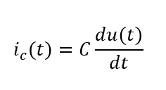
In words, a current flows through the capacitor when the voltage at the capacitor changes over time. If the voltage decreases, charge flows out of the capacitor. Conversely, the capacitor is charged when the voltage increases.
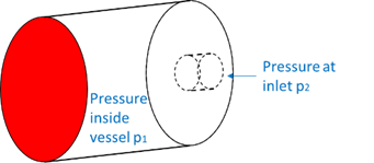
A comparable, analogous behaviour is exhibited by a compressed-air reservoir with an ideally flexible bottom. If the pressure at the inlet of the reservoir increases, compressed air flows into the reservoir until the pressure inside the reservoir equals the inlet pressure. Conversely, compressed air flows out of the reservoir when the inlet pressure falls below the reservoir pressure.
Inductance
An inductance, for example in the form of a coil, can ideally be described by the following equation:
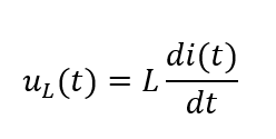
At this element, a voltage is present only when the current changes over time. In other words, the inductance opposes changes in current by inducing a voltage.
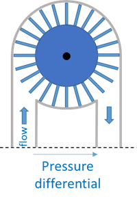
A similar behaviour can be observed in a turbine installed in a water pipeline. The inertia of the turbine opposes changes in flow by building up a pressure across the turbine.